Bim Technology Applied To Universal Studios Theme Park In Singapore
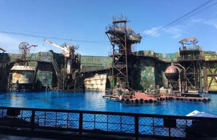
Located on Sentosa Island, Singapore, Universal Studios Singapore Theme Park is the fourth Universal Studios in the world and the first Universal Studios theme park in Southeast Asia. Universal Studios Singapore includes 8 theme areas, such as Future Water World, Lost World, Ancient Egypt, Science Fiction City, Dream World, New York City, Hollywood, Artificial Lake, and an 80000 square meter underground equipment room and parking lot. There are 24 theme amusement projects in total, 18 of which are designed or modified by Universal Studios USA specifically for Universal Studios Singapore. In addition, the Universal Studios project also includes 21 catering and retail stores, 45000 square meters of landscape decoration, gardens and roads. The entire project consists of 36 main units, covering an area of approximately 25 hectares and a building area of approximately 200000 square meters.

Engineering difficulties
The Universal Studios Singapore project is complex in structure, novel in design, and advanced in technology. The implementation of Universal Studios standards in the United States requires a high level of comprehensive ability in design and construction. The main difficulties of the project include:
The project schedule is tight. Need to complete the construction of the entire project in just 18 months
High technical requirements. The project must comply with the construction standards of multiple countries or regions such as the United States, the United Kingdom, Europe, Singapore, Australia, etc., and the steel structure needs to be redesigned according to Chinese national standards
Coordination is difficult. The scale of subcontractors in Singapore is generally small, so in the Universal Studios project in Singapore, there are more than 400 subcontractors and suppliers, which has increased the coordination work of the Project Department
Various resources are scarce. Singapore is an island country with limited supply of various resources such as materials, equipment, and subcontracting
The design adopts a parallel delegation model. Architecture, structure, electromechanical, decoration, amusement facilities, lighting effects, stage performances, and other specialties are completed by independent design consulting companies, resulting in complex interfaces and multiple conflicts in the engineering design of each specialty
Lack of experience. Developers, design institutes and various contractors are not familiar with the specific requirements of the design and construction of Universal Studios, and have no ready experience
Construction time limit. During the construction of the second phase, other attractions of Universal Studios Singapore have opened to welcome guests, and the HSE (health, safety and environment management system) requirements on the construction site are more stringent, and higher requirements are put forward for the mobilization, demobilization, storage, etc. of materials and equipment
There are many cross construction nodes. The construction site of this project is limited, there are many buildings, and the distance between each building is very small. In order to complete the project construction on time within the limited time limit, there is a large number of cross construction between various professional subcontractors, which poses higher challenges to engineering quality and personnel safety management
The existence of many difficulties and challenges such as tight construction schedule, high technical requirements, and difficult coordination seriously hinders the smooth progress of engineering construction. In response to this, the project team has decided to use BIM technology to assist construction management work, ensuring that the project can be completed on time under tight schedule requirements and ensuring engineering quality.
BIM Application Practice
In this project, BIM technology is comprehensively applied in deepening design, on-site construction, and management coordination. Based on the drawings provided by the local design institute, Revit software was used to model, and a shared platform was built to achieve independent, real-time, shared, non-interference, and mutually checked collaborative modeling operations among the three specialties of architecture, structure, and electromechanical. Combined with Naviswork and Primavera6, collision inspection, engineering quantity statistics, and construction progress simulation based on the modeling process and existing models were implemented to guide and adjust various work such as deepening design, on-site construction, and management coordination.
Architectural Modeling
Traditional CAD drawing requires the use of multiple views (plan, elevation, section, detail, design specifications, and various charts) to express the same building component, requiring multiple drawings of a building component object, which is inefficient. Moreover, each drawing is a discrete line that is not related to each other, and errors, omissions, collisions, and deficiencies between different views are inevitable. Once there are changes, multiple views need to be redrawn.
Under the BIM software platform, virtual models can be established through digital technology to represent actual buildings in the real world. The established models themselves cover a series of related information such as spatial relationships, size, and component layout of the proposed building, without the need for designers to repeatedly draw. And when errors or changes are found in the design, only the relevant parts need to be modified in the software, and other related parts will automatically update the content, reducing the workload of modification and the possibility of other errors occurring. In addition, by using the relevant commands in BIM software, various views of virtual buildings in the software can be easily obtained.
In this project, the design consulting company did not provide a BIM model, so the BIM model can only be established based on two-dimensional plane information. The existing two-dimensional plane information mainly includes electronic and printed versions, such as for electronic versions of information (. dwg format or image format). When modeling, the electronic version of two-dimensional information can be linked to Revit, and the two-dimensional plane information can be drawn into a 3D model through commands in Revit software. It can be seen that the 3D model constructed using BIM software presents the overall effect of the building intuitively and vividly.
Structural professional modeling
Traditional structural design mainly adopts the method of 2D CAD drawing. Designers select structures and arrange beams and columns based on the overall design scheme and specifications, analyze, calculate and optimize the structural design, and then deepen the reinforcement of nodes, beams, slabs, and columns. When drawing graphics, the expression of structural components is generally achieved through geometric elements such as points, lines, and surfaces, and the graphics do not contain information on the materials and materials used in the structure, which requires additional statistics.
The BIM model uses parameterized three-dimensional entity information to describe structural units, with beams, columns and other structural components as basic objects, rather than geometric elements such as points, lines, and surfaces in CAD. At the same time, simulating the real information of building structures through data technology not only includes visual information of geometric shapes, but also a large amount of non geometric information such as physical information and material information, making it convenient to view various information of building components, including three-dimensional geometric entities, from various angles and aspects.
Mechanical and Electrical Modeling
The modeling of mechanical and electrical engineering in the era of 2D CAD mainly involves designers calculating the load based on the overall design scheme and the technical indicators and system forms selected according to the specifications, determining the equipment model, and separately drawing the pipelines of various systems such as water, heating, and electricity, and then connecting them into a complete system. The two-dimensional pipeline drawings cannot reflect the spatial relationships, mutual interference, collisions, and other issues between pipelines and the overall building well.
When using BIM technology for modeling in the field of mechanical and electrical engineering, pre-processing can be carried out by referencing the preliminary design of the building model, hiding unnecessary objects, establishing load space calculation units, extracting spatial information such as area and volume, specifying the function and type of the space, calculating the design load, and selecting the type of mechanical and electrical engineering. After the mechanical and electrical selection is completed, equipment, pipelines, and connectors are arranged in the space of the building model according to the category of the mechanical and electrical system, and model diagrams of different mechanical and electrical systems are constructed and combined to form a unified mechanical and electrical system.
This project utilizes Revit MEP software for modeling in the electromechanical field. Mechanical and electrical professional modeling is carried out according to the category of mechanical and electrical systems, that is, after the mechanical and electrical pipelines and equipment of a certain system are completed, the modeling work of the mechanical and electrical pipelines and equipment of the next system is carried out until all mechanical and electrical pipelines and equipment are completed. Among them, the elevation of the electromechanical pipeline is the focus and difficulty of establishing the electromechanical model.
The spatial location between mechanical and electrical pipelines is relatively complex, and their integration with building and structural elements makes the positional relationships between various professional elements in the space more complex, increasing the possibility of errors and risks. But it is precisely through this complex and realistic spatial relationship that Revit software can achieve a valuable operation - collision detection.
Collision inspection and handling
In the design and construction of electromechanical engineering, conflicts often arise between various systems, as well as between various systems and architectural and structural specialties, resulting in a large number of design changes and on-site rework. After the introduction of BIM technology, by conducting collision checks in a virtual three-dimensional environment, collision conflicts in the design can be detected in advance, so as to timely eliminate possible collisions in the project construction process, significantly reduce the resulting changes, greatly improve the production efficiency of the construction site, and reduce cost increases and project delays caused by construction coordination.
Simulation and update of construction progress
The project design is complex and there are many participating companies, making construction project management extremely complex. Gantt charts are commonly used in current construction project management to represent progress plans. Due to their strong professionalism and low level of visualization, they cannot clearly describe construction progress and various complex relationships, making it difficult to accurately express the dynamic changes in the construction process.
This project mainly utilizes software such as Revit, Naviswork, Primavera, Excel, etc. to integrate spatial and temporal information into a visual 4D (3D+time) model, simulate the construction schedule, develop a reasonable construction plan, accurately grasp the construction progress, optimize the use of construction resources, and scientifically arrange the site. The construction schedule and resources of the entire project are managed and controlled uniformly to shorten the construction period and reduce costs.
Statistics of engineering quantity
In this project, combined with the established building information model, the quantities of individual projects, unit projects, sub projects, and sub projects of the proposed project are calculated based on the bill of quantities. On the basis of engineering quantity statistics, combined with bidding quotations and practical subcontracting procurement prices, the actual costs incurred during the construction process are compared and analyzed with the budgeted prices, and refined inspections and cost control are carried out.
In addition, during the construction process, resources such as construction water, electricity, machinery, equipment, and temporary buildings are also introduced into BIM to facilitate more effective on-site logistics organization and resource allocation; Introducing management elements such as quality and safety into BIM to facilitate more precise control of quality and safety; Introducing human factors into BIM is beneficial for better arranging process overlap, fully utilizing human resources, avoiding idle work, and simulating emergency evacuation or peak period personnel transportation, dining, and other scenarios.
The management concept and management mode of BIM in the Universal Studios project in Singapore have made full use of modern advanced information technology to try to manage construction projects, which has brought great value to the project and provided valuable experience for the application of BIM technology in construction project management.
Source: Railway BIM Alliance Note: All images in the article are reposted from the internet. Any infringement will result in deletion!


